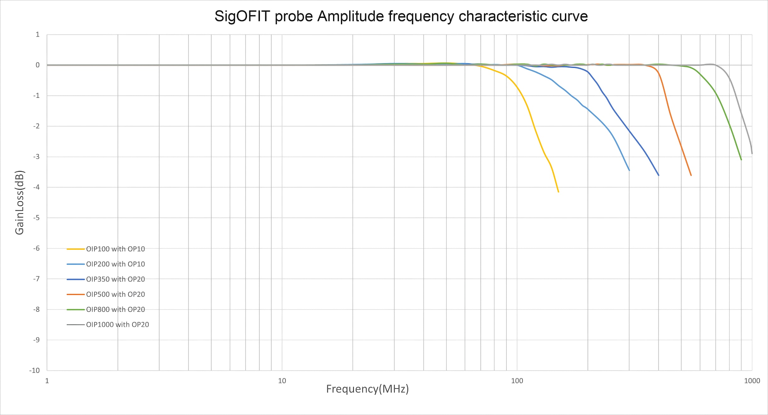
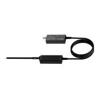
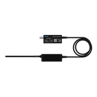
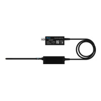
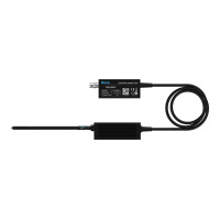
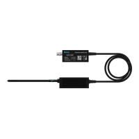
The third-generation Micsig SigOFIT™ optical isolated probe, MOIP Series, offers a bandwidth range from 200 MHz to 1GHz, enabling differential measurements from ±0.01 V up to ±20 kV. Built on Micsig’s exclusive SigOFIT™ leading technology, the MOIP Series delivers an exceptionally high CMRR, reaching up to 128 dB at 100 MHz, with an isolation voltage of up to 85 kV and an ultra-low noise floor of less than 0.3 mVrms. It reveals the complete truth of signals across its bandwidth range, serving as the ultimate referee for verifying the fidelity of signals measured by other voltage probes.
Benefits of SigOFIT Gen 3 Probes
Lasers transmit signals and provide power over fiber (no batteries needed), realizing continuous testing for 365 days with complete galvanic isolation.
Up to 1 GHz bandwidth
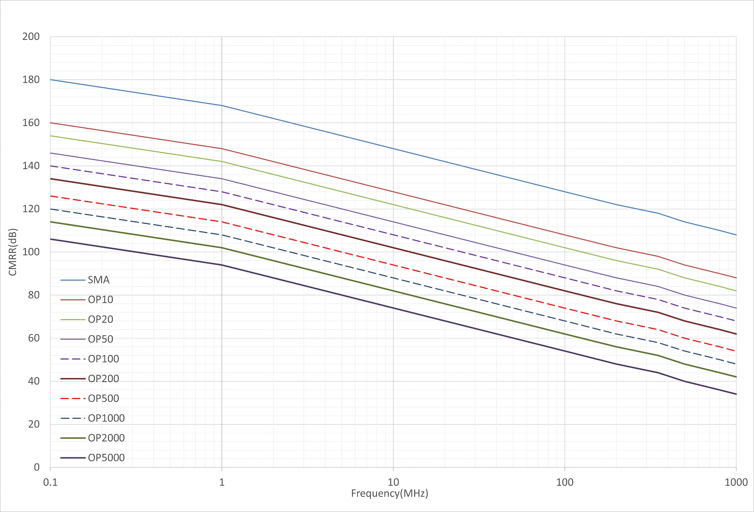
180dB CMRR at DC
Up to 128dB CMRR at 100MHz
85kVpk Common mode voltage range
Up to ±20kV differential input voltage range
≤1% DC gain accuracy
AutoZero completed in less than 1 second (Calibration-free)
Best Probe for 3rd-Gen Semiconductor
SiC & GaN devices can switch high voltages in a few nanoseconds, meaning the signal may have high-energy high-frequency harmonics.
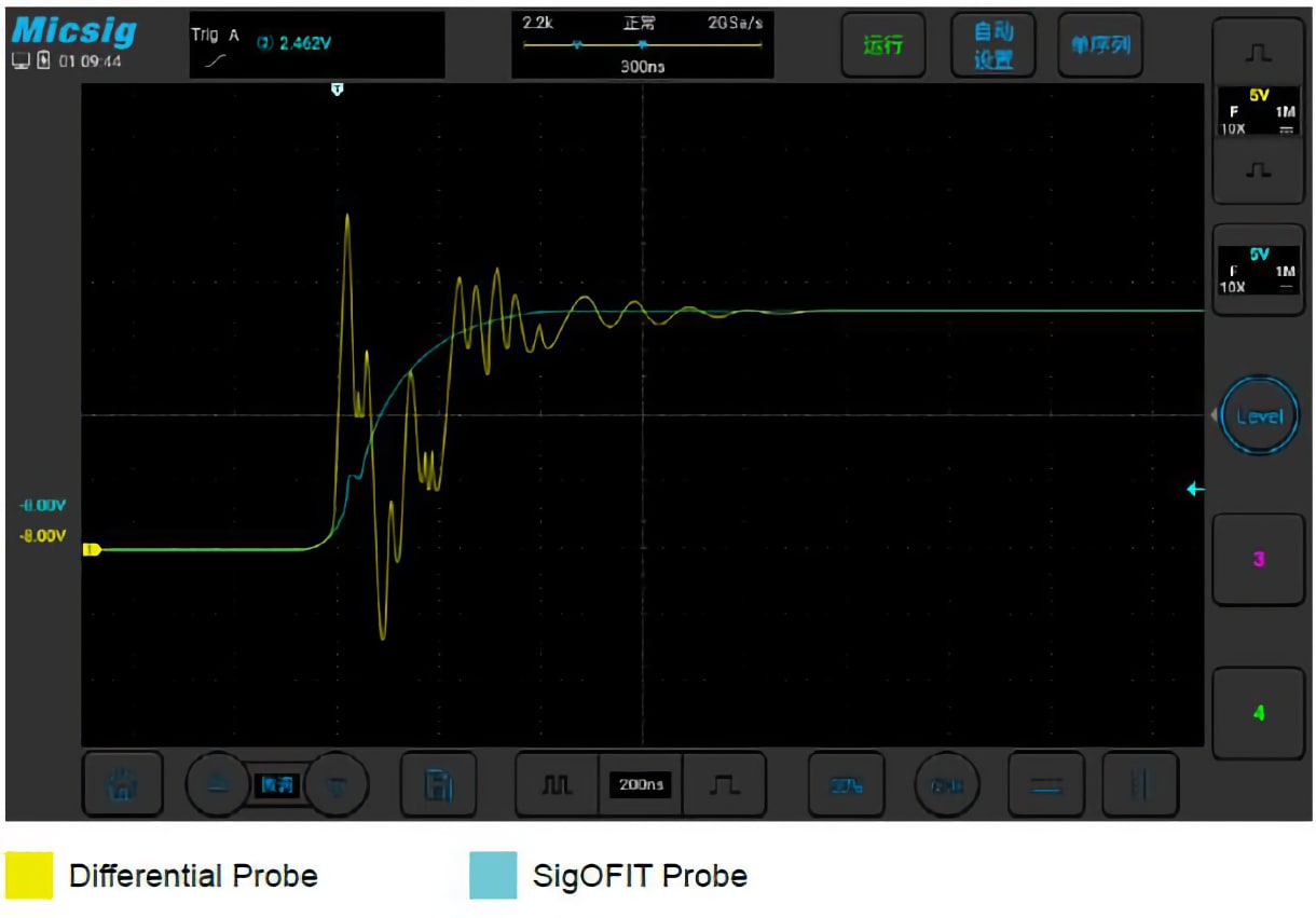
Even at the highest bandwidth, the SigOFIT probe still has nearly 100dB CMRR, perfectly suppressing the oscillation caused by high-frequency common-mode noise. The test leads are short and use coaxial cable transmission, keeping input capacitance as low as 1pF minimum, making it incredibly safe to test GaN.
Present True Signal
▲ Real-time optical power compensation ensures continuous high-fidelity waveform output
Key Applications:
Design of motor drive, power converter, electronic ballast
Design of GaN, SiC, IGBT Half/Full bridge devices
Design of inverter, UPS and switching power supply
Safety test for high voltage, high bandwidth applications













Leave a Comment