Power efficiency testing of photovoltaic inverters
Energy generation due to photovoltaic is getting more and more in focus of nowadays and future energy supply in the low-voltage grid. The DC voltage generated by the solar panels can then be stored in battery systems. Most commonly the DC voltage needs to be converted to AC to supply home appliances respectively feed the energy produced into the distribution grid. The conversion from DC to AC will be enabled by photovoltaic inverters. A typical grid connection of a solar generator is illustrated in Figure 1.

Figure 1: Typical wiring for efficiency testing of the PV inverter
To have a very low power loss during the conversion process, the inverters need to be developed with very high efficiencies. Typical efficiencies are more or less than 96%. To measure the energy produced by the solar generator, the inverter’s efficiency and the supplied energy into the grid, a power analyzer is the right tool. Depending on the solar generator string wiring, one or more strings are connected, each with its own maximum power point tracker (MPP). Solar generators respectively Inverters with higher rated power usually have a 3-phase AC output.
The LMG670 with its capability of utilizing up to 7 power channels in a single chassis, provides very precise measurement and analysis of all relevant parameters as voltages, currents, power and more of the whole photovoltaic system simultaneously without requirement of a second instrument.
Equip up to 7 power channels
The LMG600 series facilitates to equip only as many power channels as actually required for the measurement. As illustrated in Figure 2 for a grid-connected 2-string solar inverter, the LMG670 can be equipped with 6 power channels, whereby a single power channel contains 1x voltage input and 1x current input.
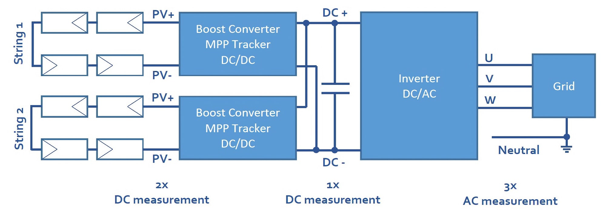
Figure 2: Measuring points of a typical grid-connected multi-string solar inverter
At least 2 power channels but typically 4 and in certain cases up to 6 or even 7 power channels are required. 7 power channels, in case a battery charging system is coupled to the PV inverter as well.
The right power channel for your requirement – Field or laboratory measurements
Typical requirements on measuring input specification:
- DC voltage range of 600V to 1000V; now also 1500V1
- AC voltage range depending on rated inverter power, 230V to 400V
- Current range depending on the rated inverter power, few 10A to few 1000A
- Bandwidth: Depending on switching frequency of the inverter, few 10kHz to few 100kHz
- Accuracy: Basic and accurate power measurement in the field: B-channel. High efficiency testing in the laboratory: A-channel
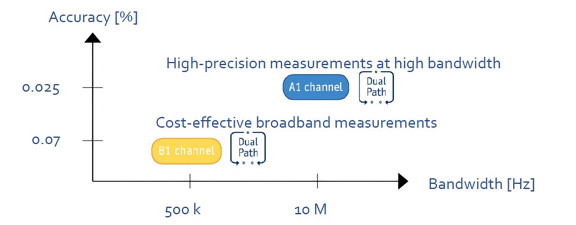
Figure 3: LMG600 Series A- and B-channel with its analogue bandwidth and accuracy
LMG600 series A- and B-channel are both capable of measuring all relevant frequency components. Depending on the required accuracy select, either A- or B-channel. Recommended is the A–channel.
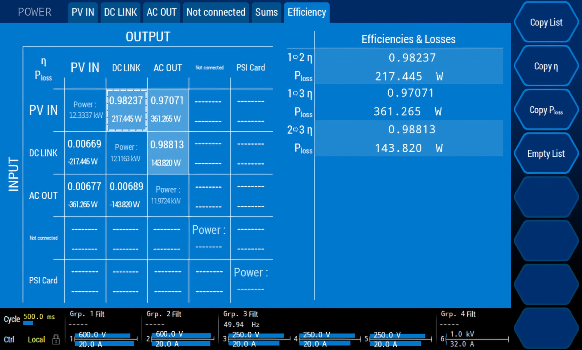
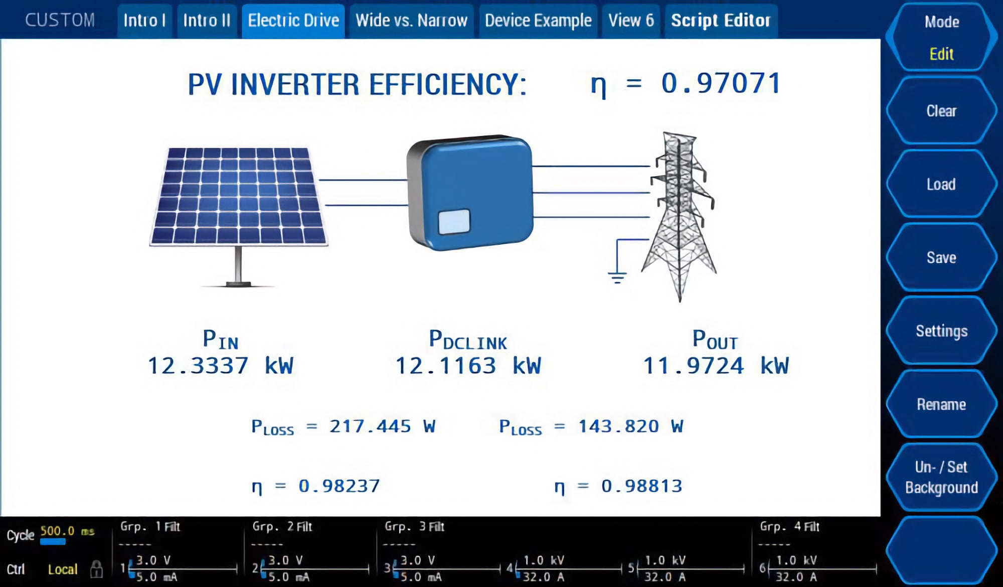
Measure the power conversion efficiency of your solar inverter
View all efficiency results between each group respectively measuring point in a single measuring menu. As a next step, build your own customized menu to see only the relevant measurands you want to have.
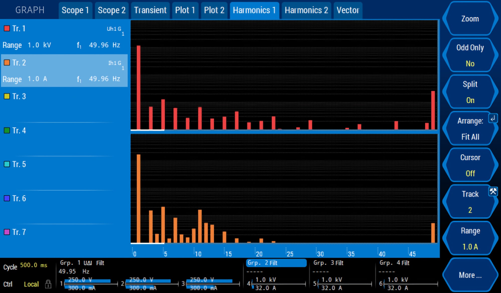
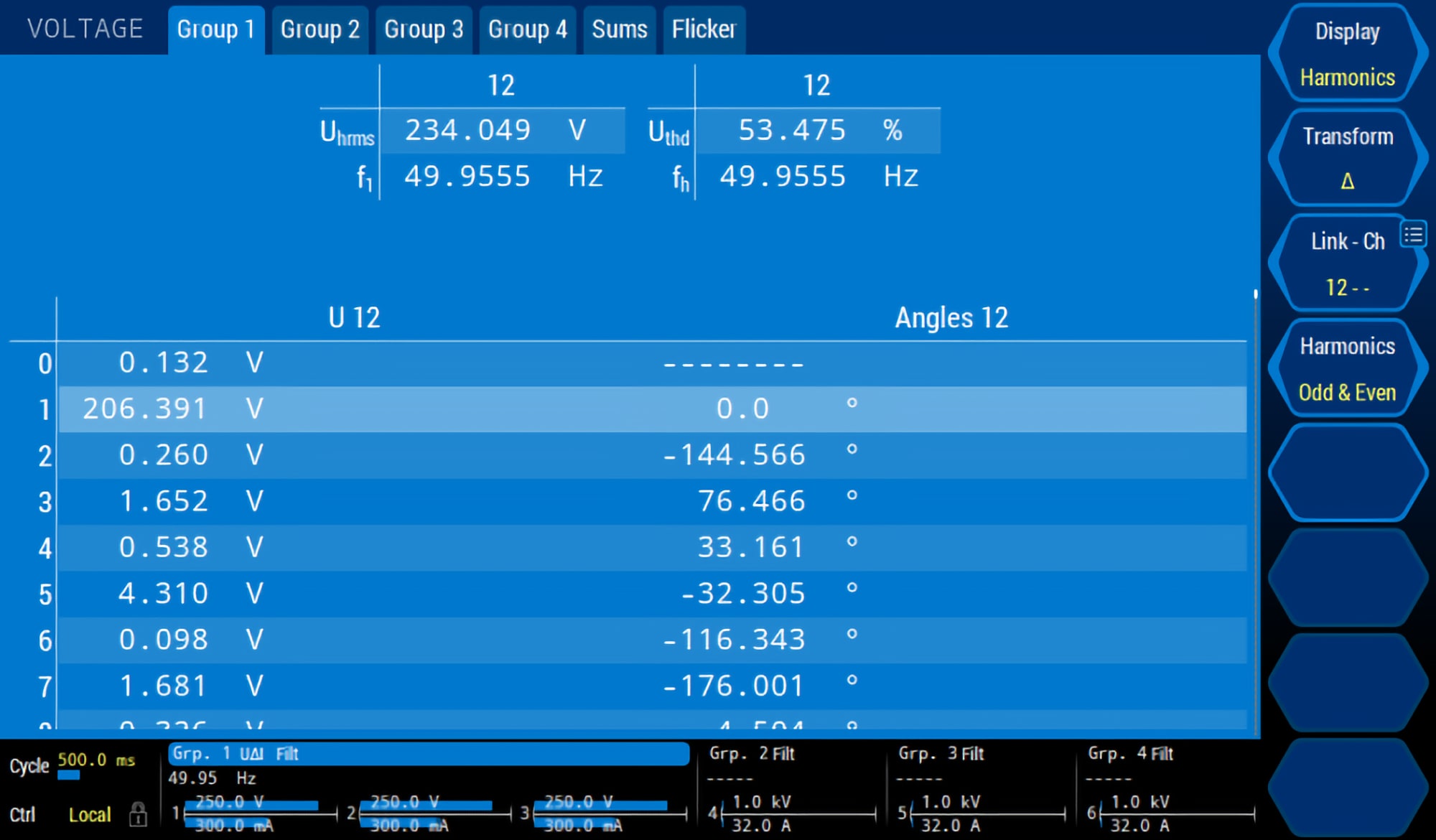
Harmonic analysis to test compliance with grid connection conditions
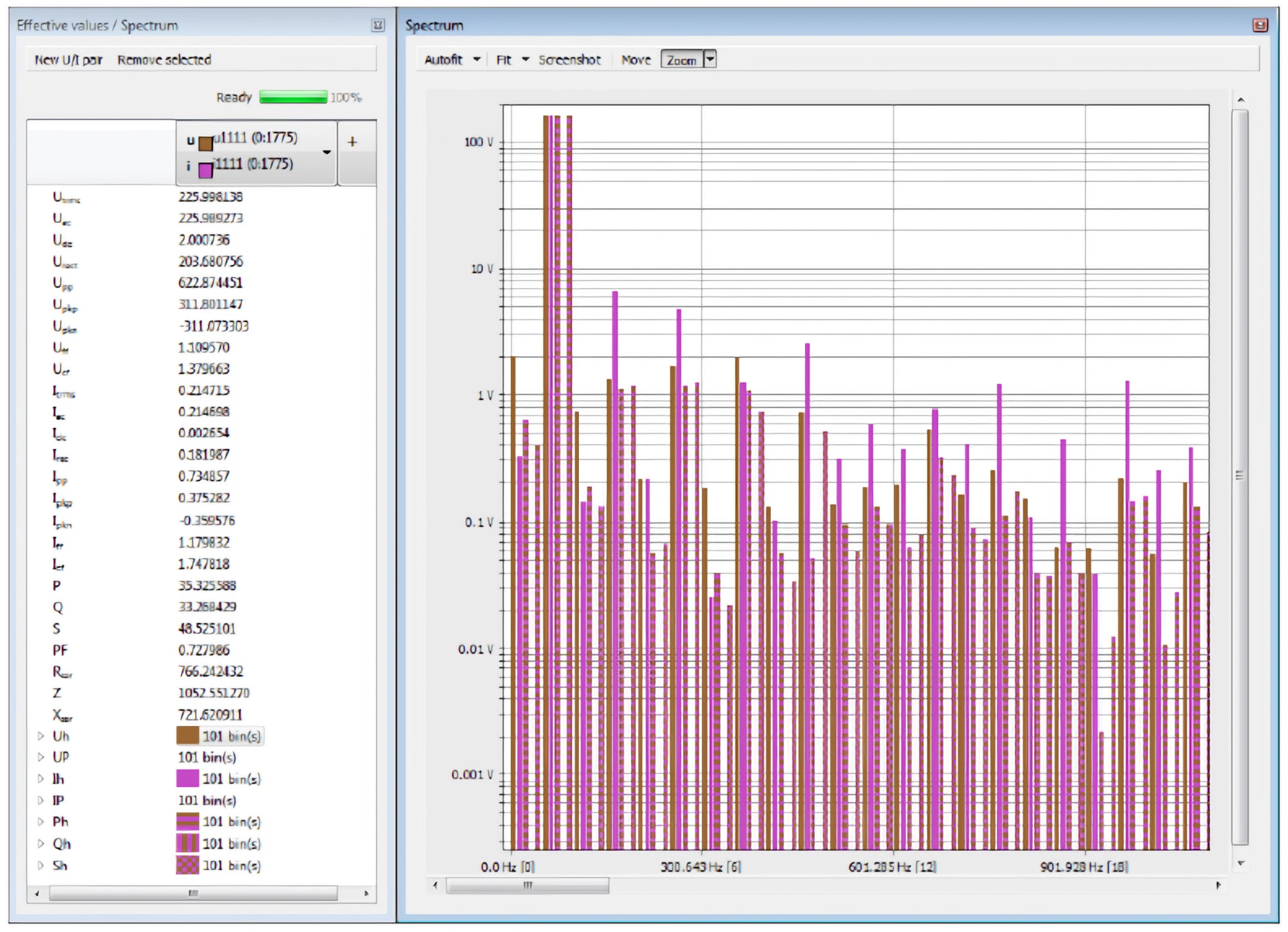
Get an overview of the harmonic content of your voltage, current and power in numeric and bargraph view to check if the harmonics and interharmonics are within the grid connection directives of photovoltaic grid supply.
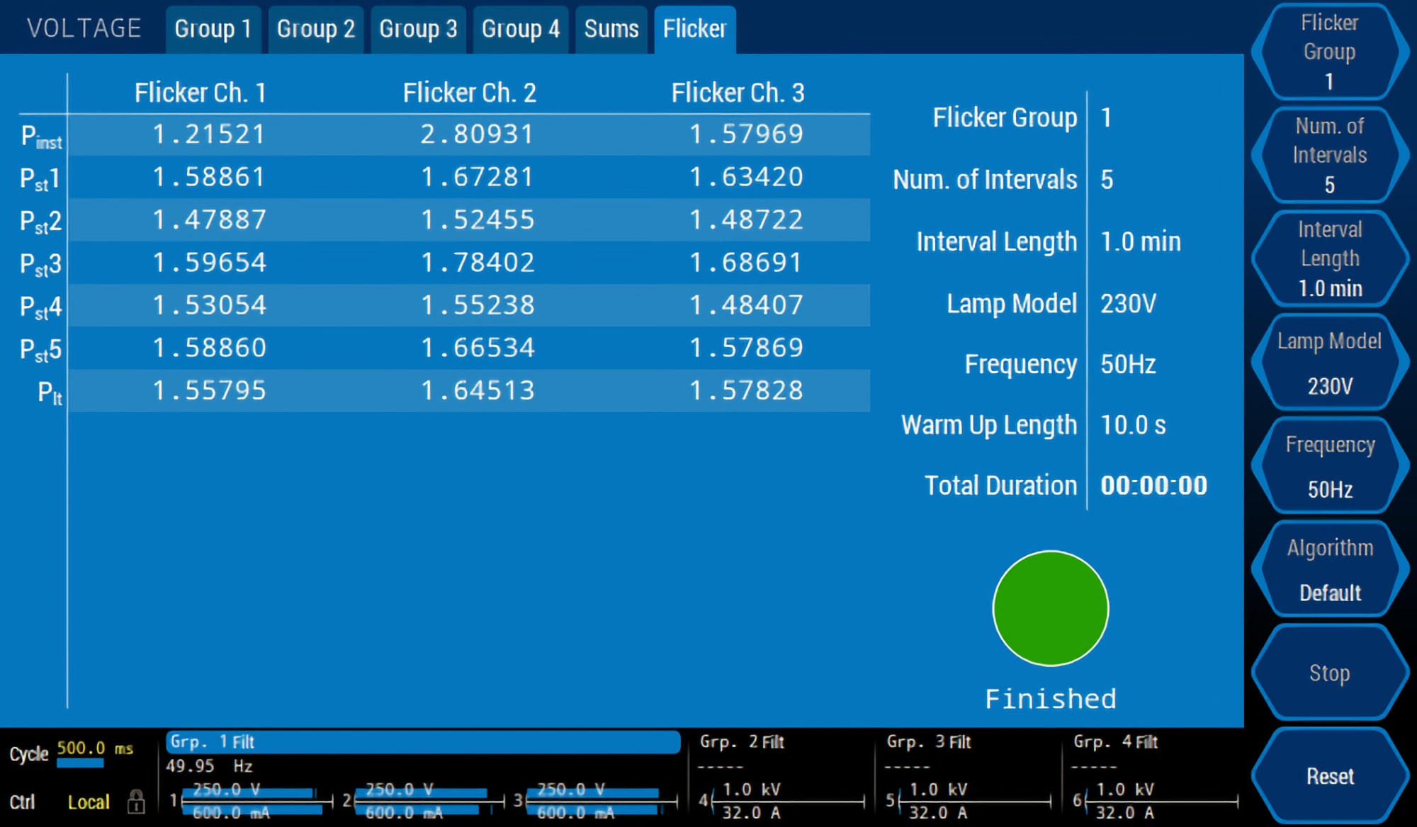
Flicker measurement to test compliance with grid connection conditions
Use the Flicker meter of the LMG600 Series to measure short term flicker Plt (perceptibility) and long term flicker Plt, considering the directives for the grid connection. These values need to be measured to check if the values are within the limits defined by the applicable standard.
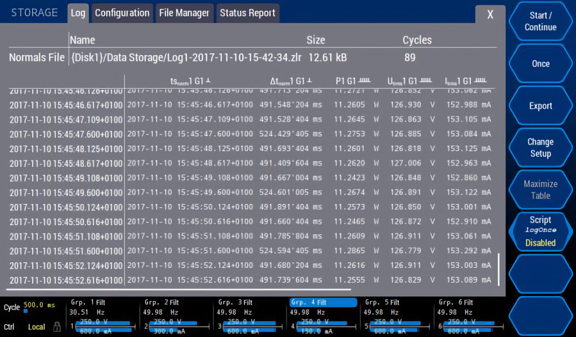
Log and post-process the power data of your solar system
Record a wide range of parameters over a long period. These data can be:
- Voltage, current, power, PF, frequency, harmonics and more
- Analog and digital processing signals: Irradiance sensor signal and more
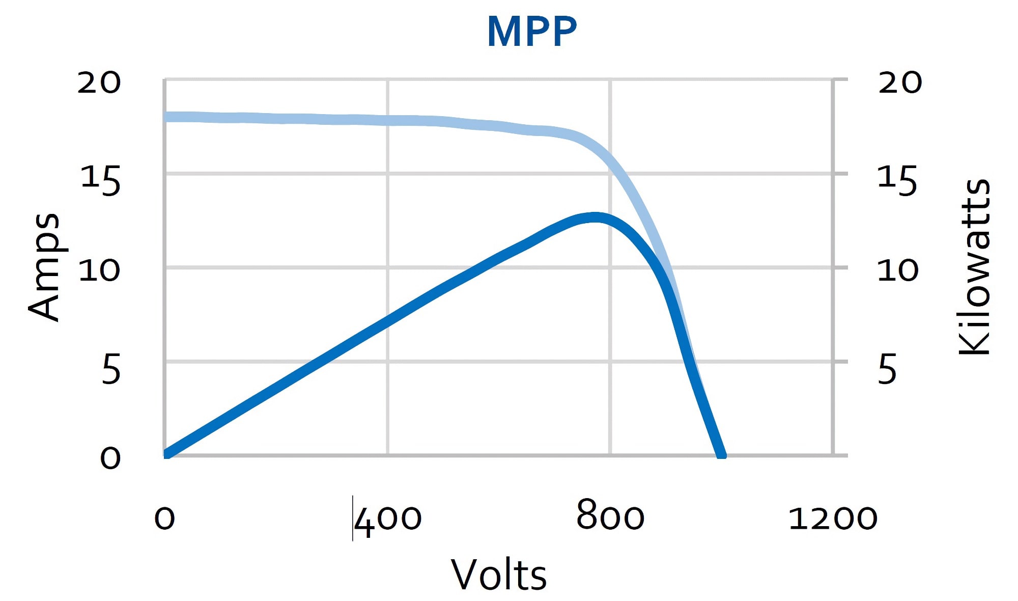
Export the recorded data into Excel, Matlab or Octave formats to post-process and view the data e.g. as MPP diagrams in common engineering tools.
View and analyze the waveform quality of the inverter output
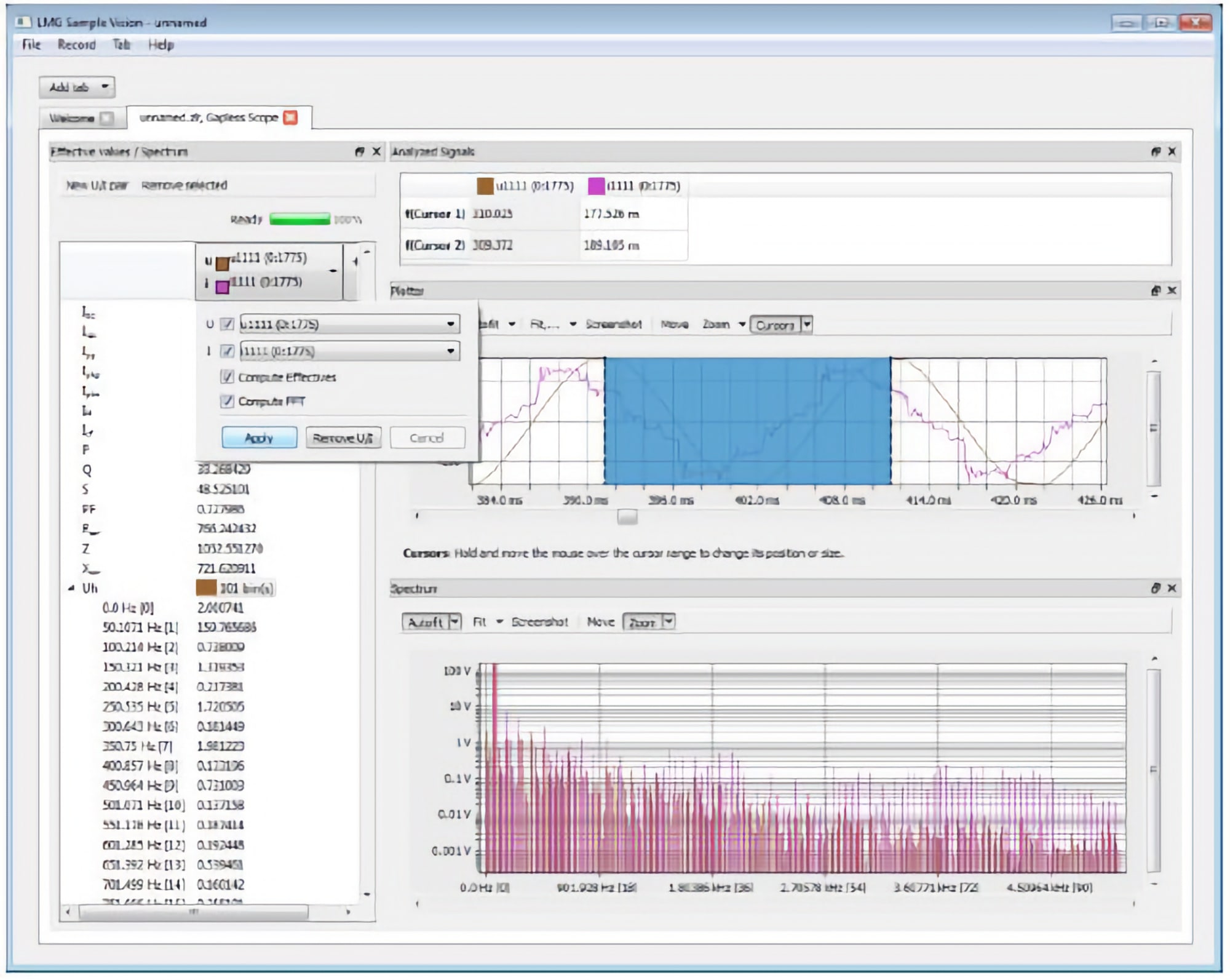
Use the software tool LMG600 Sample Vision to recording samples gapless on your PC to analyze the current and voltage waveforms formed by the DC/DC and DC/AC inverter stage.


Leave a Comment