Rohde & Schwarz LCX LCR Meter Introduction
LCR Meters Rohde & Schwarz LCX Series
The top-class in component testing
AT A GLANCE
The Rohde & Schwarz LCX LCR meters are versatile, extremely accurate and perform measurements quickly. They are ideal for challenging applications in research, development and production. Two instrument models and various options cover applications with a test signal frequency of up to 10 MHz. Internal and external bias functions, comprehensive analysis options and versatile test fixtures expand the wide range of possible applications.
The LCX100 LCR meter covers the frequency range from 4 Hz to 300 kHz. The LCX200 has an upper frequency limit of 500 kHz and can be extended to 1 MHz or 10 MHz using software options when needed. All instruments offer DC measurements as well. Internally generated voltages of up to 10 V cover most applications. Optionally, bias voltages of up to 40 V can be applied externally.
A fast logging function records all measured values up to 10 times per second.
Dynamic impedance measurements can be performed using the advanced analysis function. In these sweep measurements, the impedance values are determined for a series of frequency values or other parameters.
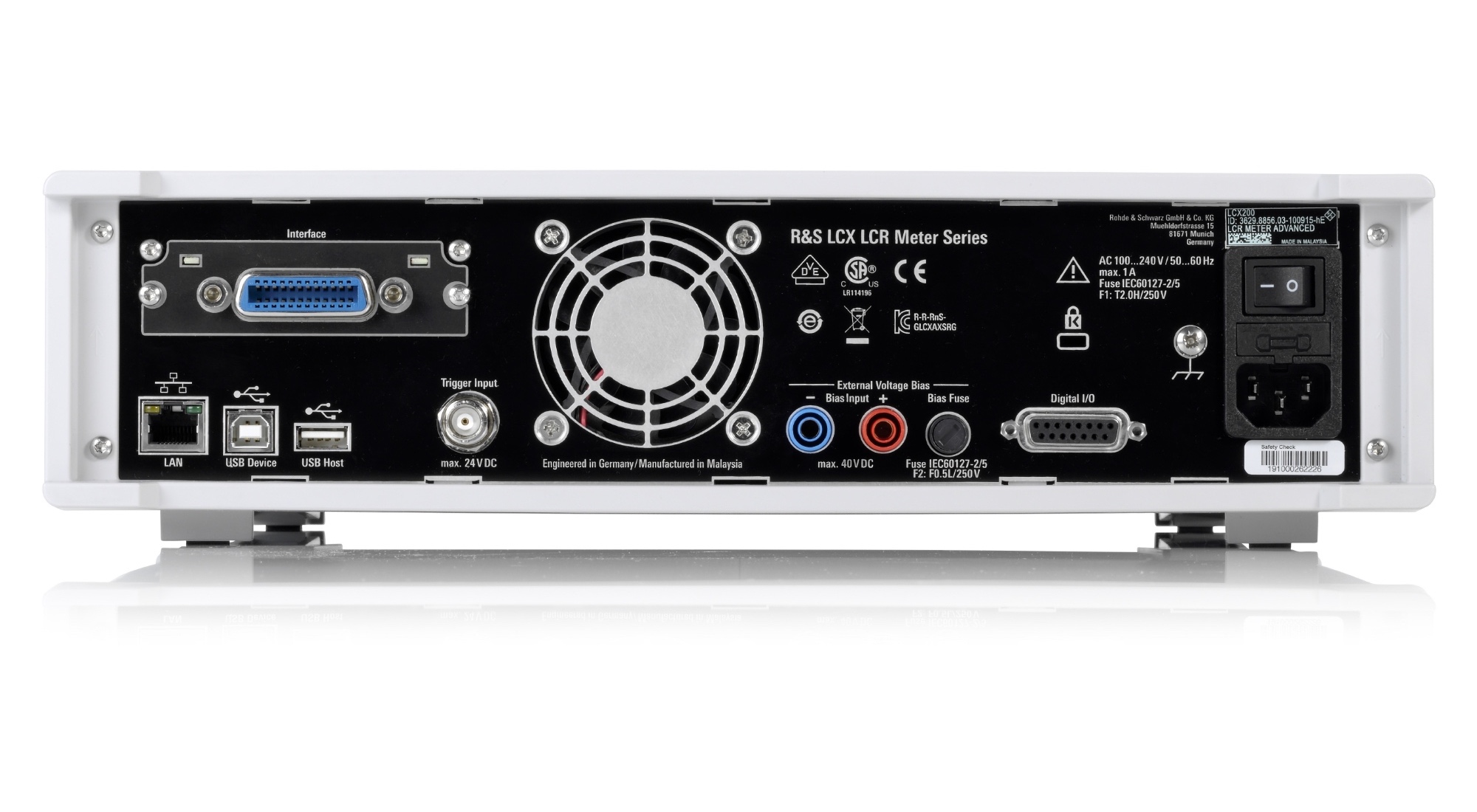
Measurements can be triggered and controlled externally via digital I/O ports. The binning function enables the measured components to be sorted by their values into up to eight categories.
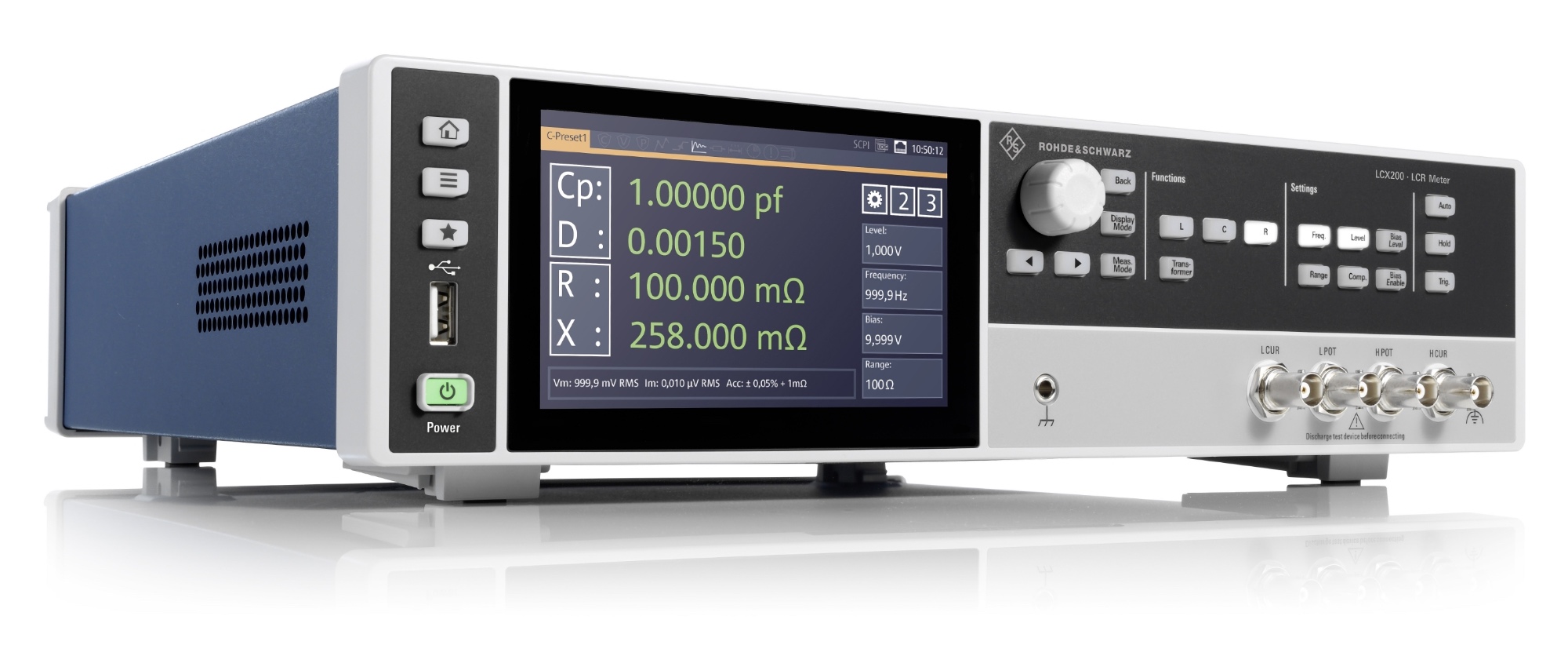
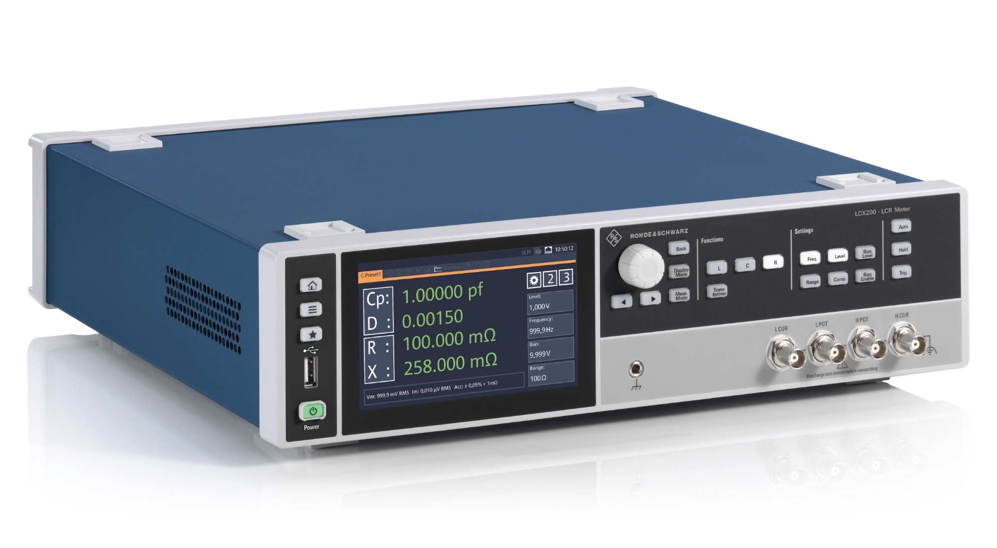
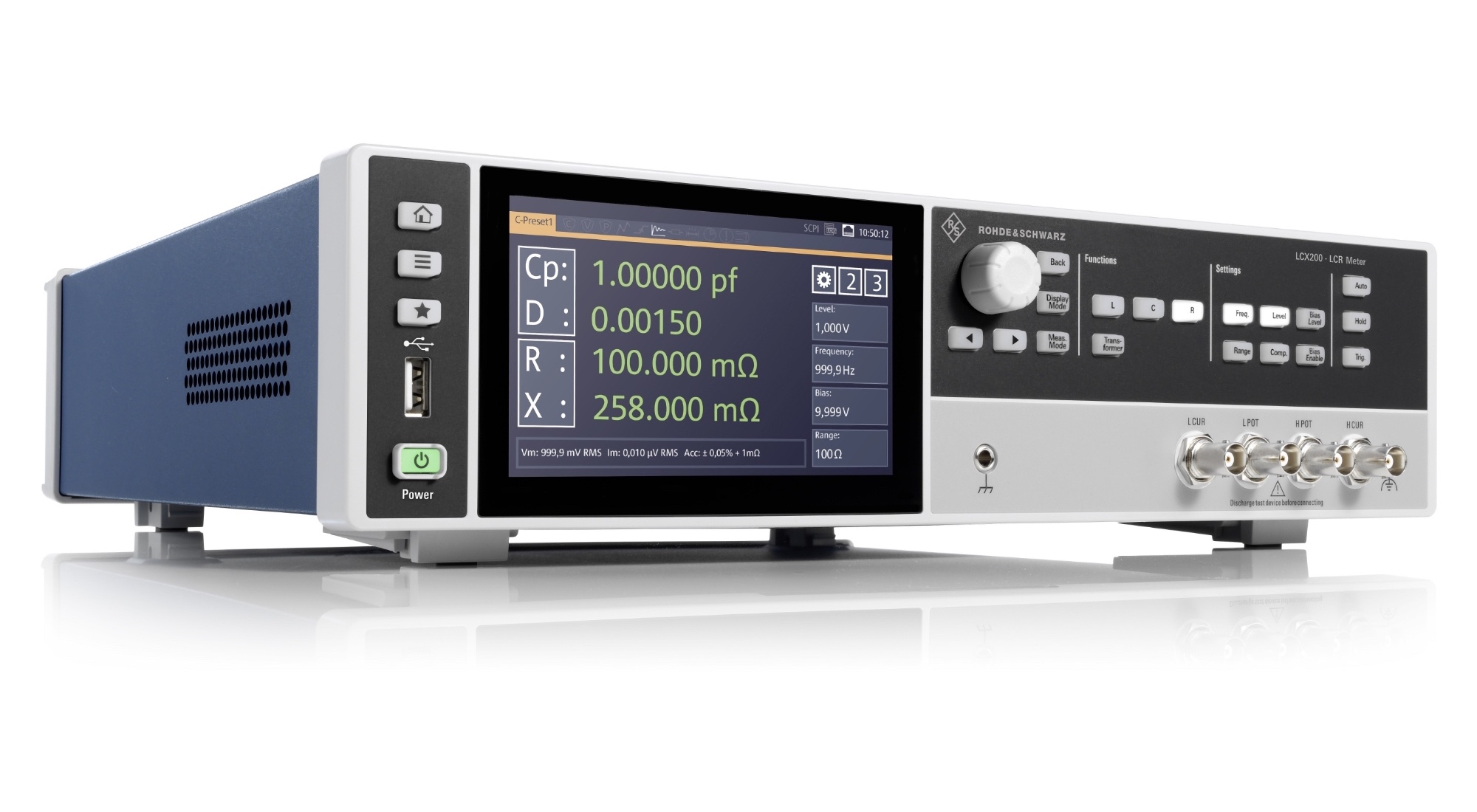
The large capacitive touchscreen is the central element for modern and intuitive operation of the instruments and enables the graphical display of the measurement results.
Remote controllability and rack installation predestine the R&S®LCX for system applications.
Key facts
| Features |
LCX100 |
LCX200 |
| Test signal frequency |
DC, 4 Hz to 300 kHz |
DC, 4 Hz to to 500 kHz, software options up to 10MHz |
| Test signal voltage |
100 mV to 10 V |
< 1 MHz: 100 mV to 10 V,
> 1 MHz: 100 mV to 2 V |
| DC bias voltage (internal) |
0 V to +10 V |
| DC bias current (internal) |
0 mA to 200 mA |
| External DC bias voltage, input |
0 V to +40 V |
| Source impedance |
100 Ω, 10 Ω |
| Measurement range |
100 mΩ to 100 MΩ |
| Basic accuracy for impedance measurements |
0.05% |
BENEFITS AND KEY FEATURES
Universal LCR meter
► Fast, accurate and versatile
► Selectable frequency range
► Test signals for all requirements
► DC bias
► Measurement functions
► Data logging function
Options for advanced applications
► LCX-K106 Software option for advanced analysis functions
► LCX-K107 Software option for Digital I/O ports and binning function
► LCX-K108 Software option for extended bias functions
► LCX-K201 / LCX-K210 Software option for Frequency upgrade to 1MHz/10MHz, for LCX200
Easy operation
► High-resolution touchscreen
► Graphical representation of measurements
► Save and recall instrument settings
Test fixtures
► LCX-Z1 Test fixture for axial/radial lead type devices
► LCX-Z2 Kelvin clip lead
► LCX-Z3 Test fixture for SMD components
► LCX-Z4 Test tweezers for SMD components
► LCX-Z5 Transformers and transducers test cables
► LCX-Z11 BNC extension, 1m length
Ideal for use in labs and test systems
► Tailored for use in labs and system racks
► Full remote capabilities
► Advanced instrument design: compact form factor, quiet operation
UNIVERSAL LCR METER
Fast, accurate and versatile
Both R&S®LCX models combine high measurement speed, accuracy and versatile measurement capabilities. This makes them the ideal instruments for standard measurements in development, for material analysis in research as well as for fast production testing. With their broad measurement ranges, they also cover applications with extremely low and extremely high impedances.
Three measurement times are available:
► Fast: ≤ 15 ms
► Medium: ≤ 100 ms
► Slow: ≤ 500 ms
The basic accuracy for impedance measurements is ±0.05%, and for phase measurements ±0.03°.
Selectable frequency range
All R&S®LCX models measure under DC conditions. The AC range already begins at 4 Hz. The upper frequency limit on the LCX100 is 300 kHz. In its base configuration, the LCX200 is designed for a maximum frequency of 500 kHz; this frequency limit can, however, be extended to 1 MHz or 10 MHz. This means that the ideal instrument is available for any given application and budget.
Test signals for all requirements
Test signals can be generated from 100 mV to 10 V and deliver a current of up to 200 mA. The instruments have a selectable output impedance of 100 Ω or 10 Ω. The actual current flow and the voltage applied are measured using the monitor function.
DC bias
In many applications, an adjustable DC bias is necessary in order to measure C and L components at different operating points. The LCX100 and LCX200 generate a DC bias voltage of up to 10 V. As an option, it is also possible to set a DC bias current (up to 200 mA). DC bias voltages of up to 40 V can be applied at an external connection on the rear panel (LCX-K108 option) using a standard DC power supply, for example an R&S®NGA.
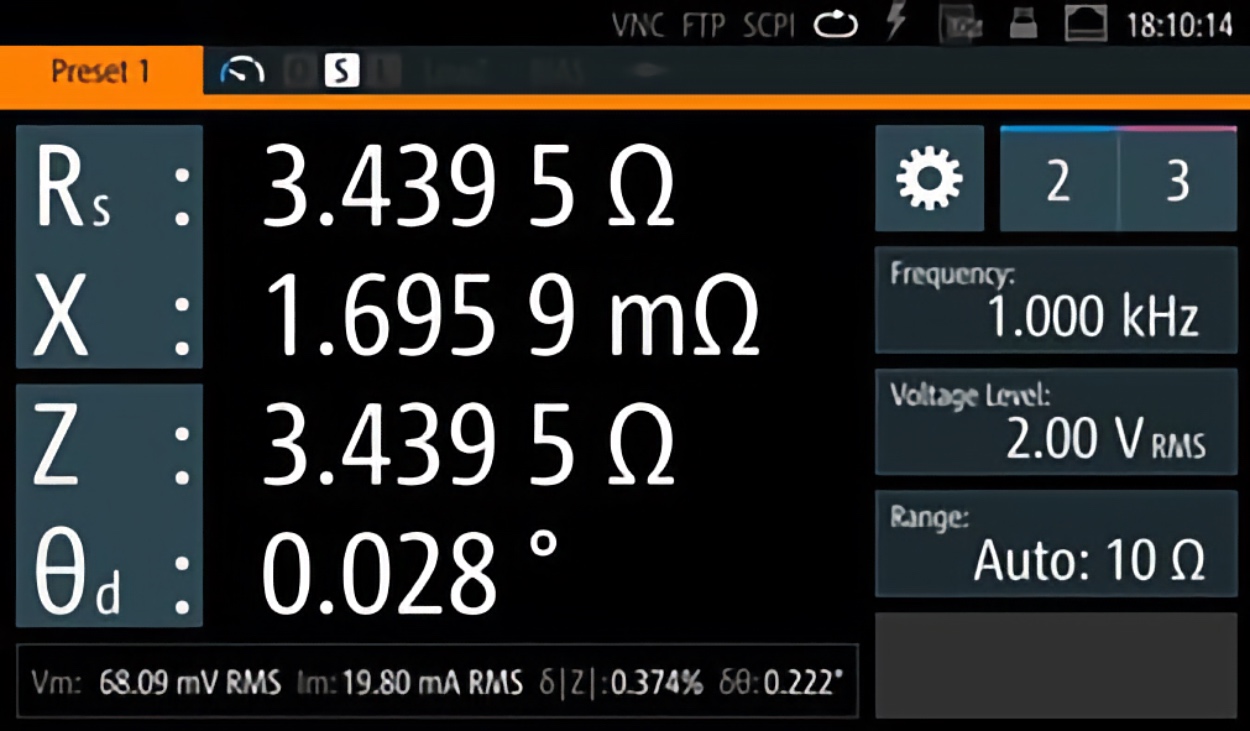 Up to four measurement parameters can be shown on the display at the same time
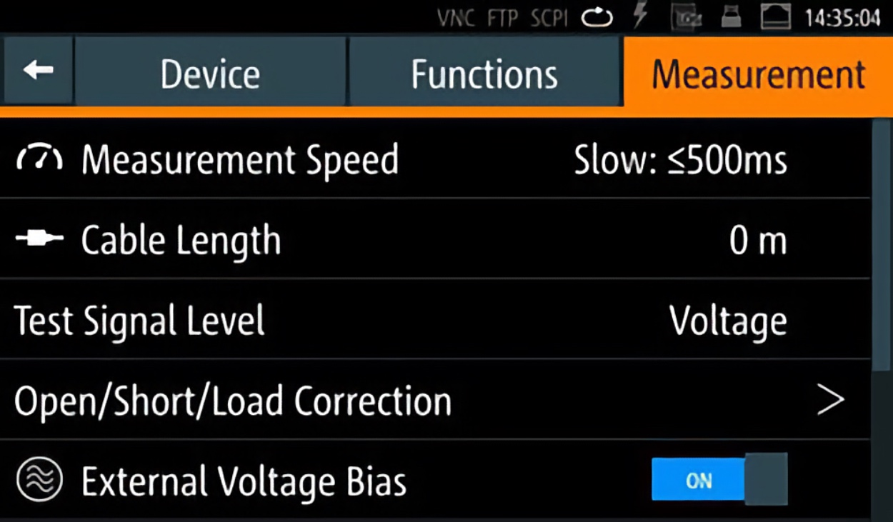 Test signals and measurement functions can be configured as required
Measurement functions
In addition to the many different impedance measurements, the two R&S®LCX LCR meters are also able to measure transformers as well as resistances with DC voltage. The display can show up to four measurement parameters at the same time, and the measurement functions can be selected in pairs from the following table:
Data logging function
The R&S®LCX LCR meters provide a fast logging function for recording all measured values. The data can be saved on an external USB flash drive or transferred to an external PC via USB or LAN. With a data rate of up to 10 sample/s, the measured values are available every 100 ms.
| List of measurement functions |
| Cp |
Capacitance value measured with parallel-equivalent circuit model |
| Cs |
Capacitance value measured with series-equivalent circuit model |
| Lp |
Inductance value measured with parallel-equivalent circuit model |
| Ls |
Inductance value measured with series-equivalent circuit model |
| D |
Dissipation factor |
| Q |
Quality factor (inverse of D) |
| G |
Equivalent parallel conductance measured with parallel-equivalent circuit model |
| Rp |
Equivalent parallel resistance measured with parallel-equivalent circuit model |
| Rs |
Equivalent series resistance measured with series-equivalent circuit model |
| Rdc |
Direct current resistance |
| R |
Resistance |
| X |
Reactance |
| Z |
Impedance |
| Y |
Admittance |
| Θd |
Phase angle of impedance/admittance (degree) |
| Θr |
Phase angle of impedance/admittance (radian) |
| B |
Susceptance |
| M |
Mutual inductance |
| N |
Turns ratio |
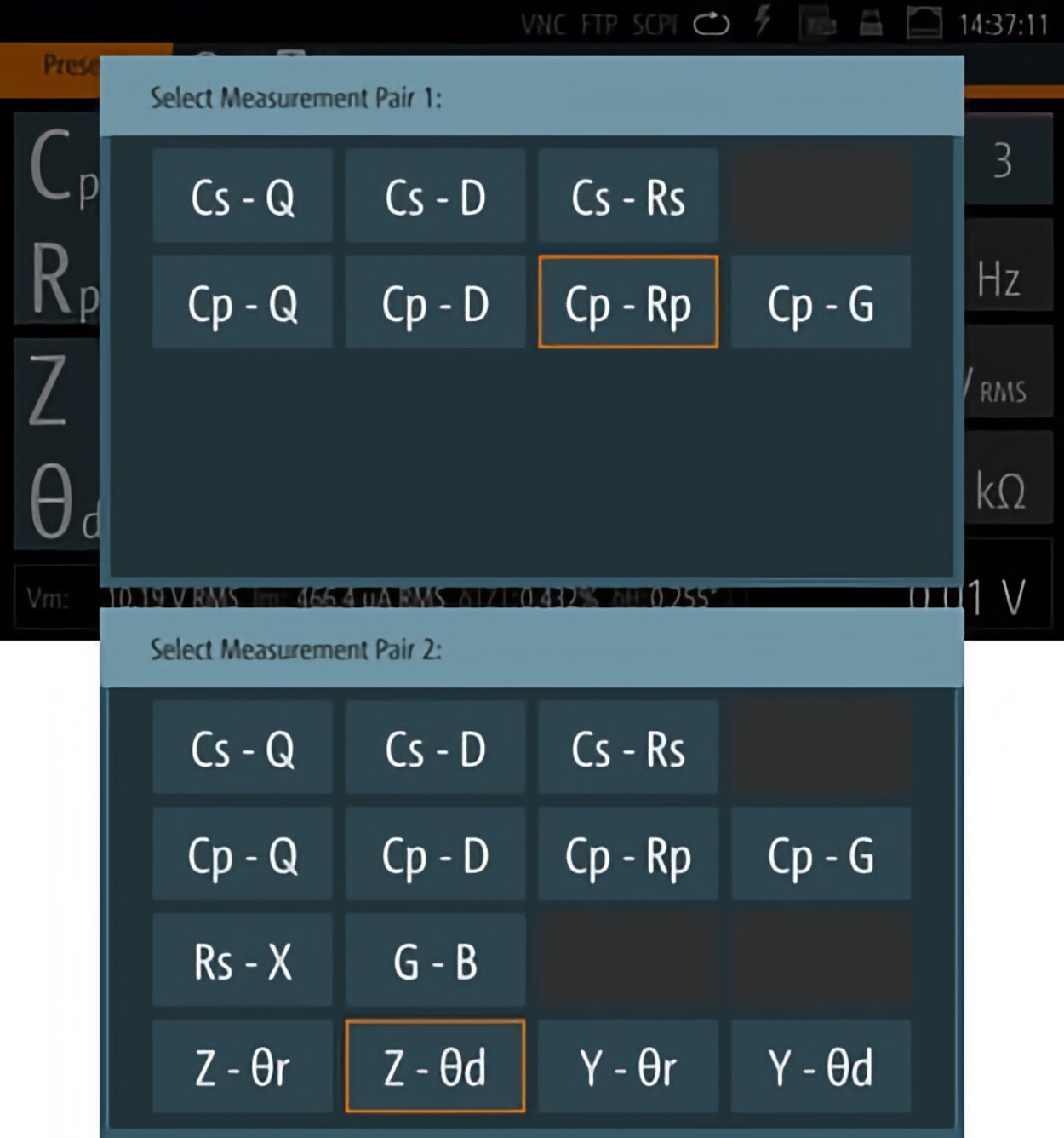
Measurement functions can be selected in pairs


Leave a Comment