-
U heeft nog geen producten in uw winkelwagen.
U heeft nog geen producten in uw winkelwagen.
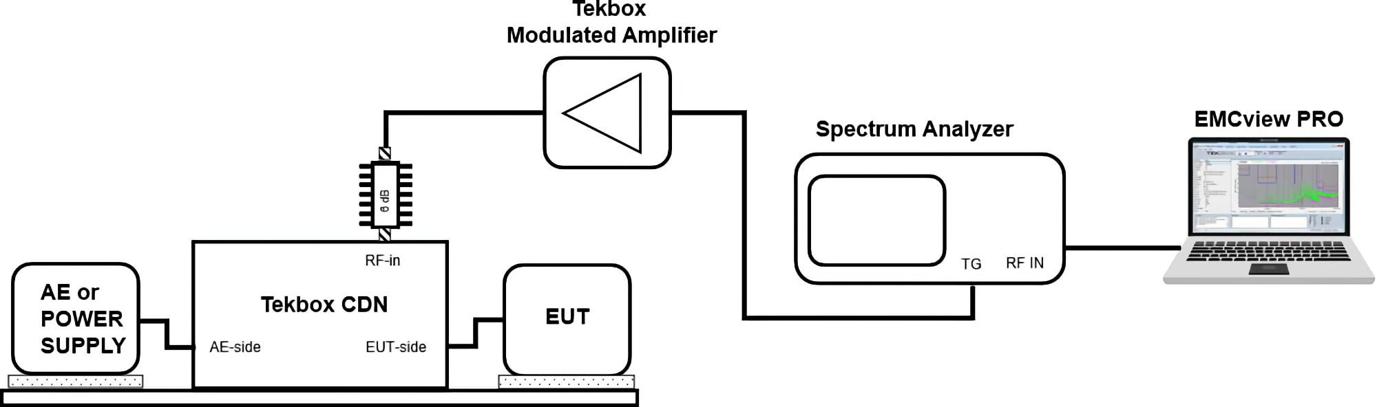
EN 61000-4-6 calibration set up using EMCview PRO

The specified test levels are open circuit voltages at the EUT port of the CDN.
The voltages measured during calibration must be multiplied by 3 to allow for the 50 Ohm to 150 Ohm conversion and again by 2 to reach the open circuit voltage.
Hence, the measured voltage at the output of the 150 Ohm to 50 Ohm adapter is 1/6 th the voltage of the desired stress level. In logarithmic figures, the measured voltage is 15.5 dB lower than the open circuit voltage.
Example: Test level 2
U0= 3V RMS open circuit voltage at the EUT port of the CDN = 3V/6 = 0.5V RMS at the output of the 100 Ohm to 50 Ohm adapter
The required power at the output of the modulated amplifier is:
U0/6 [dBm] + CDN insertion loss + 6 dB (Attenuator) + 5.1 dB (80% AM RMS)
Assuming 10 dB insertion loss for the CDN, the required RF power is:
7 dBm + 10 dB + 6 dB + 5.1 dB = 28.1 dBm = 0.65 Watt
During calibration, EMCview Pro will make a stepped sweep, for each frequency adjusting the tracking generator level in order to achieve 7 dBm + 5.1 dB -30 dB = -17.9 dBm at the spectrum analyzer input. The tracking generator level table will then be used to set levels during the actual immunity test.
The typical insertion loss of a CDN with attached 150 Ohm to 50 Ohm adapter is 10 dB.
Adding the 6 dB attenuator and 5.1 dB for the AM RMS conversion results in a quasi-insertion loss of 10 dB + 6 dB + 5.1 dB = 21.1 dB
For open circuit voltages of 1V, 3V and 10V, the corresponding power at the output of the 150 Ohm to 50 Ohm adapter is -2.6 dBm, 7 dBm, 17.4 dBm RMS CW. Add 5.1 dB to cover the RMS power of 80% AM modulation.
Consequently, the required power at the input of the 6 dB attenuator for class 1/2/3 is 18.5 dBm / 28.1 dBm / 38.5 dBm.
The table below reflects the insertion loss versus frequency of a real CDN in order to set the required input power for the TBMDA5.
| Frequency [MHz] |
TBMDA5 output power to achieve stress level 1 [dBm] |
Corresponding TBMDA5 input power [dBm] |
TBMDA5 output power to achieve stress level 2 [dBm] |
Corresponding TBMDA5 input power [dBm] |
| 0.15 | 17.3 | -22 dBm | 27.3 | -12 dBm |
| 0.5 | 16.6 | -23 dBm | 26.6 | -13 dBm |
| 1 | 16.9 | -22 dBm | 26.9 | -12 dBm |
| 10 | 17.8 | -22 dBm | 27.8 | -12 dBm |
| 100 | 18.7 | -19 dBm | 28.7 | -9 dBm |
| 230 | 20 | -19 dBm | 30 | -9 dBm |
Table - measured input power settings for the TBMDA5 in order to achieve stress level 1 and 2
The maximum output power of the TBMDA5 is approximately 3 dB short with respect to power level 3. As a compromise, the 6 dB attenuator could be replaced by a 3 dB attenuator.
EMCview PRO has the capability to automatically adjust the tracking generator level in order to achieve the desired stress level voltage. The output is a calibration table, which is loaded and applied during the immunity test.
EN 61000-4-6 immunity test set up using EMCview PRO


Leave a Comment