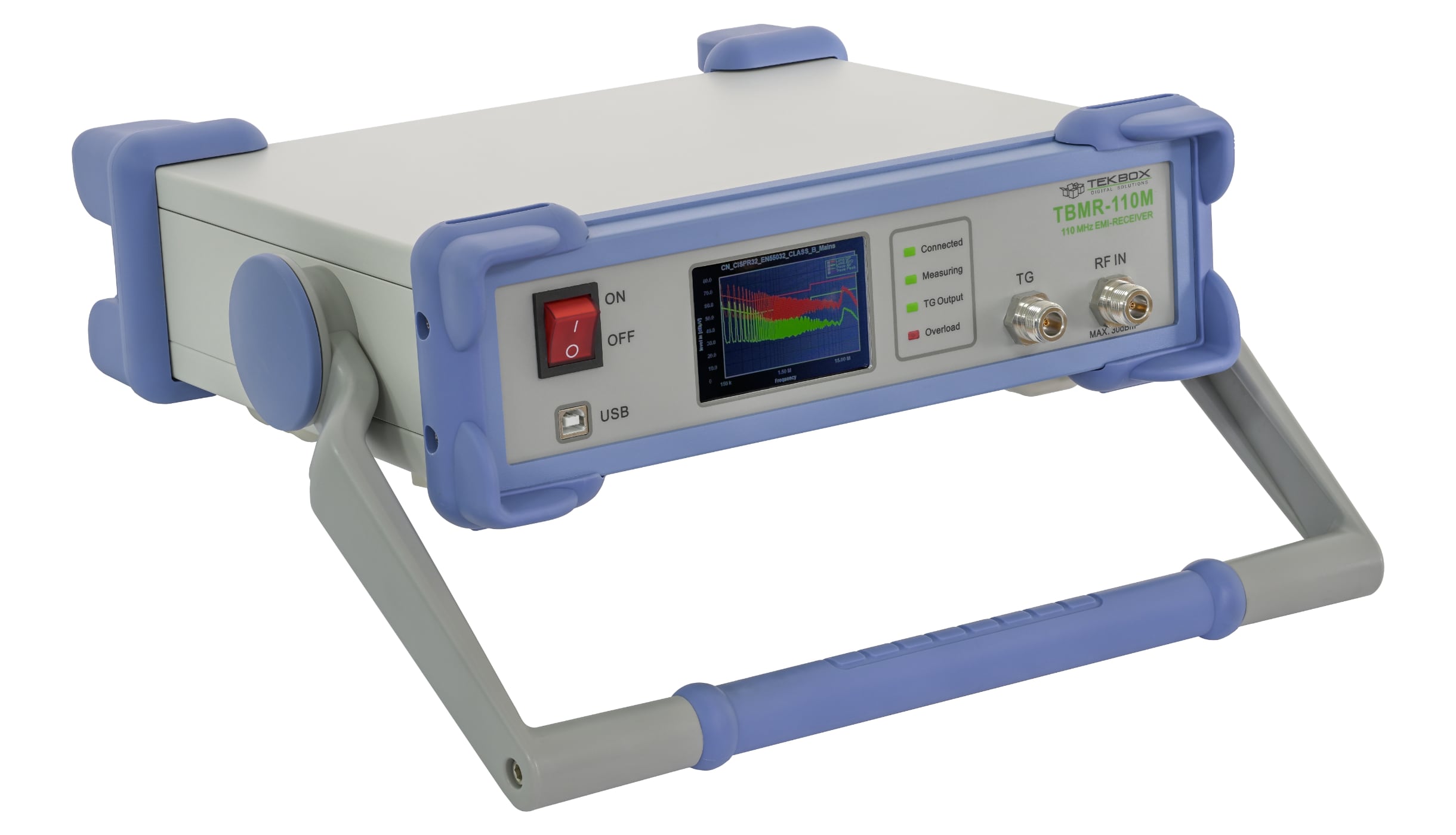
TekBox TBMR-110M EMI Receiver Introduction
International EMC Standards require various spectrum measurement methods and equipment to ensure that the EUT's electromagnetic emissions do not exceed the specified limits. The TBMR-110M EMI Analyzer is designed to carry out conducted emission measurements. Its affordability and versatility make it a perfect tool for engineers doing pre-compliance measurements during the development process. Its ease of use also enables importers of electronic items to periodically assess if their suppliers supply consistent quality in terms of EMC compliance, without having to outsource it to test laboratories. High accuracy, versatility and high-speed measurements are only a few of the many features.
Tekbox TBMR-110M comes with:
- 1 x Type-A to type-B USD cable
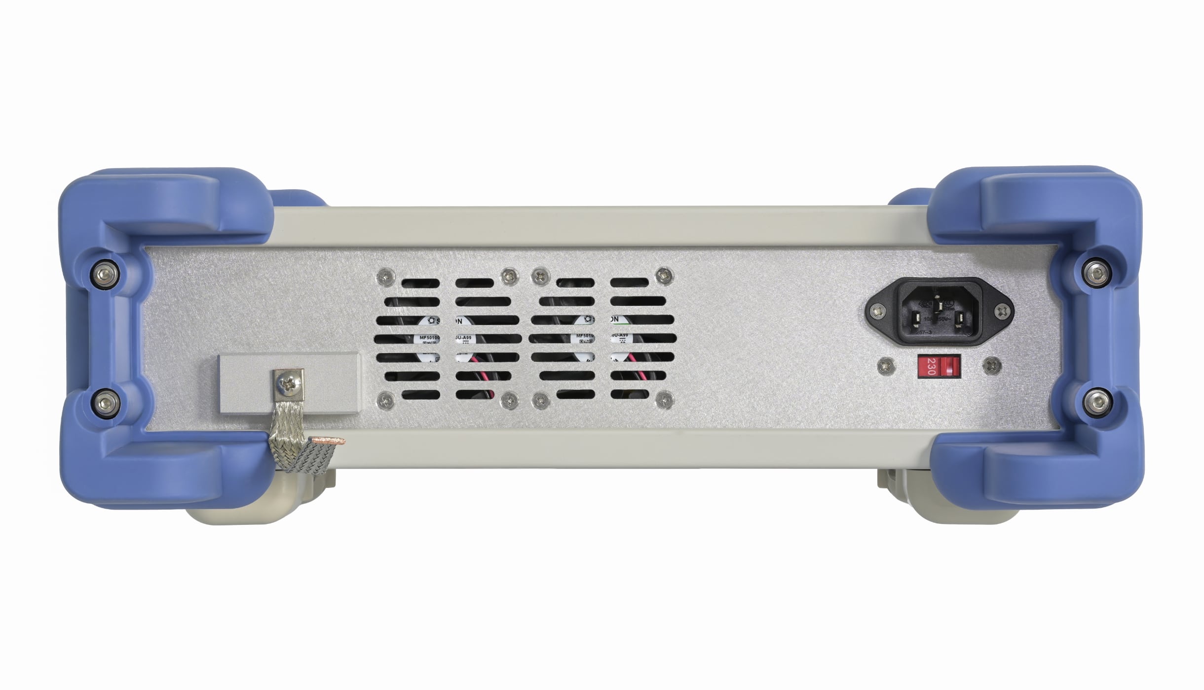
- 1 x Country specific IEC power cord
- 1 x (TBFL1) Transient Limiter
- EMCview software
Main features:
EMI Analyzer 1 Hz - 110 MHz (Measurement Receiver)
- -162 dBm/Hz noise floor down to 1 kHz
- 7-band hardware pre-selector filter bank
- 30 dBm maximum input power
- CISPR-16, ANSI and MIL-STD compliant detectors
- Peak, Quasi-Peak, Average, CISPR-Average, RMS and CISPR-RMS detectors working in parallel
- Sweep, STFFT and direct parallel resolution bandwidth setting (-3 dB and -6dB)
- Numerous predefined Standards, ready to load and use
- Pre-measurement with selective Peak measurement
- Direct fast compliant STFFT measurement
- Many pre-defined transducers, antenna factors and various other compensation files
- Many data manipulation, display and documentation features
- Direct control from EMCView or standalone operation
- Quick load of predefined setups
Spectrum Analyzer 1 Hz - 110 MHz
- True DC – 110 MHz measurement range
- Tracking Generator
- 0.1 Hz to 3.5 MHz arbitrary RBW and VBW setting
- Zero Span operation with time domain triggering
- Linear, log amplitude and frequency display
- Sweep, STFFT and direct parallel resolution bandwidth setting
- Parallel RMS, Pos./Neg. peak and average detector
- Trace Memory option, normalization
- Equation based trace display
- Peak hold
- Noise marker, max and band power display
- Quick load of predefined setups
Tracking Analyzer 1 Hz - 110 MHz
- Linear and logarithmic sweep
- -50 dBm to 0 dBm adjustable TG power
- 120 dB dynamic range
- Use of power correction file and level correction file
- Quick load of predefined setups
Oscilloscope 250 MS/s, DC - 110 MHz
- 1 ns/DIV to 1 s/DIV horizontal resolution
- Interpolated sampling up to 4 GS/s
- Real-time Sampling up to 250 MS/s, 14 Bit
- Up to 16 MS sampling size
- Various Trigger options
- Vertical CIC Filter option for noise reduction
- Many automatic measurement features
Demodulator
- Direct demodulation into the PC sound system
- FM, AM and SSB demodulator
- Adjustable bandwidth, center frequency and demodulator parameters
- Automatic demodulation parameter measurements
IQ Stream Generator
- GNU-Radio data source
- Directly stream floating point I and Q data into file or network
- Adjustable center frequency and bandwidth
Remote Control
- Direct remote control of the EMI Analyzer over network
- Text based protocol
- EMCview compatible
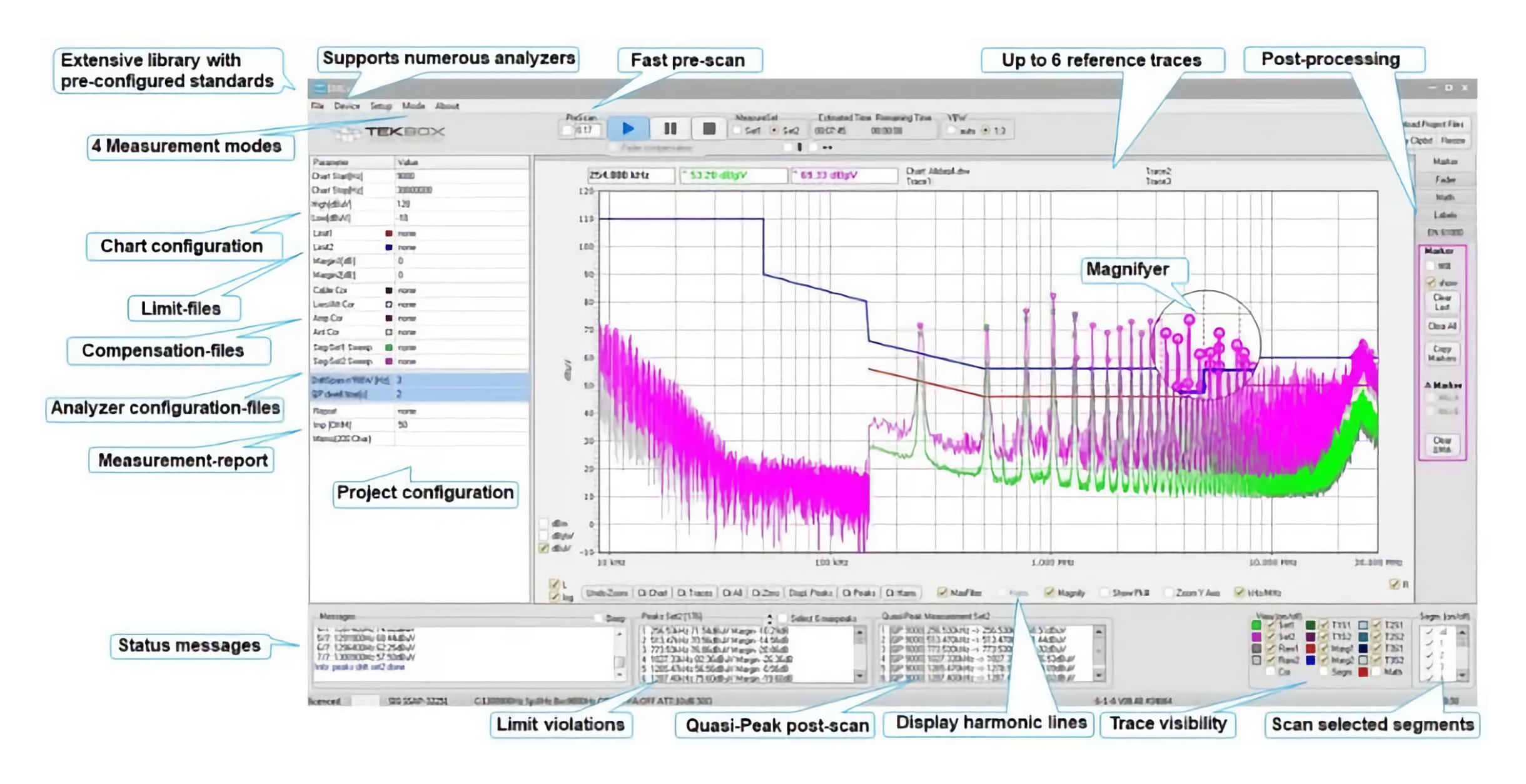
The Tekbox EMC compliance PC software EMCview is a user-friendly EMC pre-compliance testing of radiated and conducted emissions. It is a perfect complement for automated testing using LISNs, RF current probes, measurement antennas and TEM Cells.
A built-in amplitude correction enables correction and conversion coefficients for cables, amplifiers, attenuators, LISNs, TEM cells, antennas, RF current probes, filters and any other component in the signal chain.
There is no need for a time-consuming setup. The SW is ready for measurements straight after installation. All emission related standards and a few automotive manufacturer standards are pre-configured in corresponding project files. The project files take care of all necessary settings to conduct standard compliant measurements. Besides using pre-configured projects, the user can easily create his own projects using a built in editor or any simple text editor.
The graph supports two complete measurement runs such as for example Average / Quasi-Peak or Peak / Quasi Peak and in addition a fast Quasi-Peak scan of critical peaks. Graphs can be saved and overlayed with newer measurements to track and document design modifications.
Furthermore, EMCview together with the GPS receiver can be used to carry out RF-coverage measurements. An export feature creates KML files which links the result to google maps.
Immunity testing is supported with dedicated menus, controlling the tracking generator of the spectrum analyzer.
EMCview PRO, offers real-time measurement support for spectrum analyzers with real-time capability. Furthermore, EMCview PRO offers advanced conducted immunity testing features for spectrum analyzers with tracking generators. The customer can select between a standard EMCview license or EMCview PRO. Users with a standard EMCview license have the option to upgrade to EMCview Pro with the (EMCview-St-Pro-Update) model.
| Parameter |
Description |
Value / Range |
Remark |
| Operating Voltage |
Mains Voltage Range |
100-120 VAC / 200 - 240 VAC, 50-60 Hz |
Mains voltage selection switch |
| Operating Temperature |
|
0 °C - 40 °C |
|
| Storage Temperature |
|
-20 °C - 60 °C |
|
| Frequency Range |
Oscilloscope |
DC - 110 MHz |
True DC coupled |
| |
Spectrum Analyzer |
1 Hz - 110 MHz |
Max. 0V DC |
| |
EMI Analyzer |
1 Hz - 110 MHz |
Max. 0V DC |
| |
Tracking Analyzer |
1 Hz - 110 MHz |
Max. 0V DC |
| Reference Frequency accuracy |
Initial accuracy after 30 minutes warm-up |
+/- 10 ppm |
|
| RF Input connector |
|
50 Ohm, Type-N |
|
| RF input VSWR |
|
< 1 : 1.15 |
10 ... 30dB att. |
| |
|
< 1 : 1.5 |
0 ... 30dB gain |
| Maximum RF input level |
Attenuation / gain |
+30 dBm/137dBµV/7V |
20dB/30dB att. |
| |
dependent |
+25 dBm/132dBµV/4V |
10 dB att. |
| |
Negative att. = gain |
+15 dBm/122dBµV/1.25V |
0 ... -30dB att. |
| Input RF attenuator |
|
0 - 30 dB in 10 dB steps |
|
| Input LNA |
|
0 - 30 dB in 10 dB steps |
|
| Amplitude Accuracy |
DC - 110 MHz |
Better +/- 0.8 dB |
at 18°C - 28°C |
| Noise (DANL) |
f = 10 Hz |
- 132 dBm typical |
RBW = 1Hz |
| |
f = 100 Hz |
- 144 dBm typical |
RBW = 1Hz |
| |
f = 1 kHz |
- 149 dBm typical |
RBW = 1Hz |
| |
f = 10 kHz |
-156 dBm typical |
RBW = 1Hz |
| |
f = 100 kHz |
- 160 dBm typical |
RBW = 1Hz |
| |
f > 1MHz - 110 MHz |
- 162 dBm typical |
RBW = 1Hz |
| Intercept Point 2 |
f = 10 MHz |
+ 50 dBm typical |
ATT = 0 dB |
| Intercept Point 3 |
f1 = 32 MHz, f2= 33 MHz |
+ 43 dBm typical |
ATT = 30 dB |
| |
|
+ 24 dBm typical |
ATT = 0 dB |
| |
|
- 6 dBm typical |
ATT = -30 dB |
| Resolution Bandwidth |
|
0.1 Hz - 3.5 MHz |
arbitrary |
| Video Bandwidth |
|
0.1 Hz - 3.5 MHz |
arbitrary |
| Pre-Selector Filter Bank |
|
7 Bands + Bypass |
6th order bandpass |
| Sampling Rate |
|
250 MSPS, 14 Bit |
|
| Detector |
|
RMS, pos./neg. Peak, Average, Quasi Peak, CISPR Average, CISPR RMS |
According to CISPR-16-1-1 and Mil Std. 461 |
| Processing |
|
Sweep, STFFT, parallel sweep |
|
| Tracking Generator frequency stability |
|
+/- 25 ppm |
|
| Tracking Generator amplitude stability |
|
better +/- 0.5 dB |
|
| Tracking Generator amplitude range |
DC - 100 MHz |
-50 dBm to 0 dBm |
|
| |
100 MHz - 110 MHz |
-50 dBm to -10 dBm |
|
| Dimensions / weight |
|
L x W x H: 33 x 38 x 12 cm; 5.2 kg |
|


Leave a Comment